
The Union Manufacturing X Plane Series Feature Study
The Union Mfg. Co. Union X Plane Series is the single most important Series of woodworking tools
produced by the company.
This series of iron planes was loved early on and is still recognized as one of the best engineered and finest woodworking planes available. Many planes have been made since the introduction of the X Plane, going as far back as Roman times, some overly simple and others overly complex. The X Plane falls right down the middle and is a feat of engineering that hides its talents deep within the inner workings of the plane. On the surface you see what appears to be a very simple yet elegant design. Don’t let its simplicity lull you into thinking this plane is mediocre in any way.
While the Stanley Bedrock is the plane that gets most of the attention due to its makers name recognition, the Union X Plane is a beast that was so good in the early 1900’s it was considered a serious threat to the sales and marketing departments at Stanley. Stanley would eventually go on to purchase Union Plane Co from the heads at Union Manufacturing Company around 1921. It was likely a move to remove this specific plane from the market in the long term to protect their highest end woodworking plane, the Bedrock Series. That being said even Stanley enjoyed the rock solid sales performance these beautiful planes achieved. They continued using the leftover castings and components, as well as adding others to continue the sales until the overstock was exhausted. During the X Plane tenure at stanley The engineers even solved one of the concerns on this series of planes. (SEE Type 4)
X Plane Sizes as originally manufactured.
X0
Union Mfg Co X No 0
Smooth Plane, 5-1/2 Inches Long
1-1/4 Inch Cutter
X3

Union Mfg Co X No 3
Union Mfg Co X No 3
Smooth Plane, 8 Inches Long
1-3/4 Inch Cutter
X4-1/4

Union Mfg Co X No 4-1/4
Smooth Plane, 9 Inches Long
2 Inch Cutter
X4-1/2

Union Mfg Co X No 4-1/2
Smooth Plane, 10 Inches Long
2-3/8 Inch Cutter
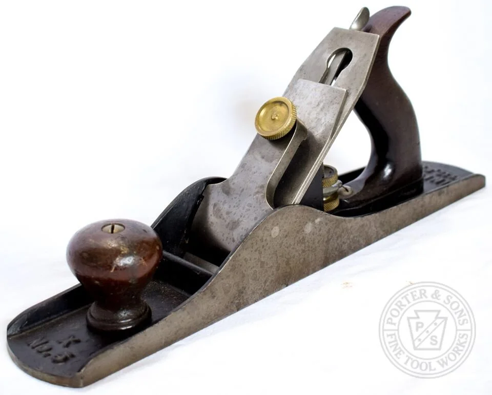
X5A

Union Mfg Co X No 5A
Jack Plane, 15 Inches Long
2-1/4 Inch Cutter
X7

Union Mfg Co X No 7
Jointer Plane, 22 Inches Long
2-3/8 Inch Cutter
X2

Union Mfg Co X No 2
Smooth Plane, 7 Inches Long
1-5/8 Inch Cutter
X4

Union Mfg Co X No 4
Union Mfg Co X No 4
Smooth Plane, 9 Inches Long
2 Inch Cutter
X4-3/8

Union Mfg Co X No 4-3/8
Smooth Plane, 9-1/2 Inches Long
2-1/4 Inch Cutter
X5

Union Mfg Co X No 5
Union Mfg Co X No 5
Jack Plane, 14 Inches Long
2 Inch Cutter
X6

Union Mfg Co X No 6
Fore Plane, 18 Inches Long
2-3/8 Inch Cutter
X8

Union Mfg Co X No 8
Jointer Plane, 24 Inches Long
2-5/8 Inch Cutter
About the Patents
Patent No. 746,285 / Patented Dec 08, 1903
Patent No. 746,286 / Patented Dec 08, 1903
Patent No. 763,721 / Patented Jun 28, 1904
Patentees: John W. Carleton and George E. Trask
Assigned to: Union Manufacturing Company

Signatures from the Patent Application
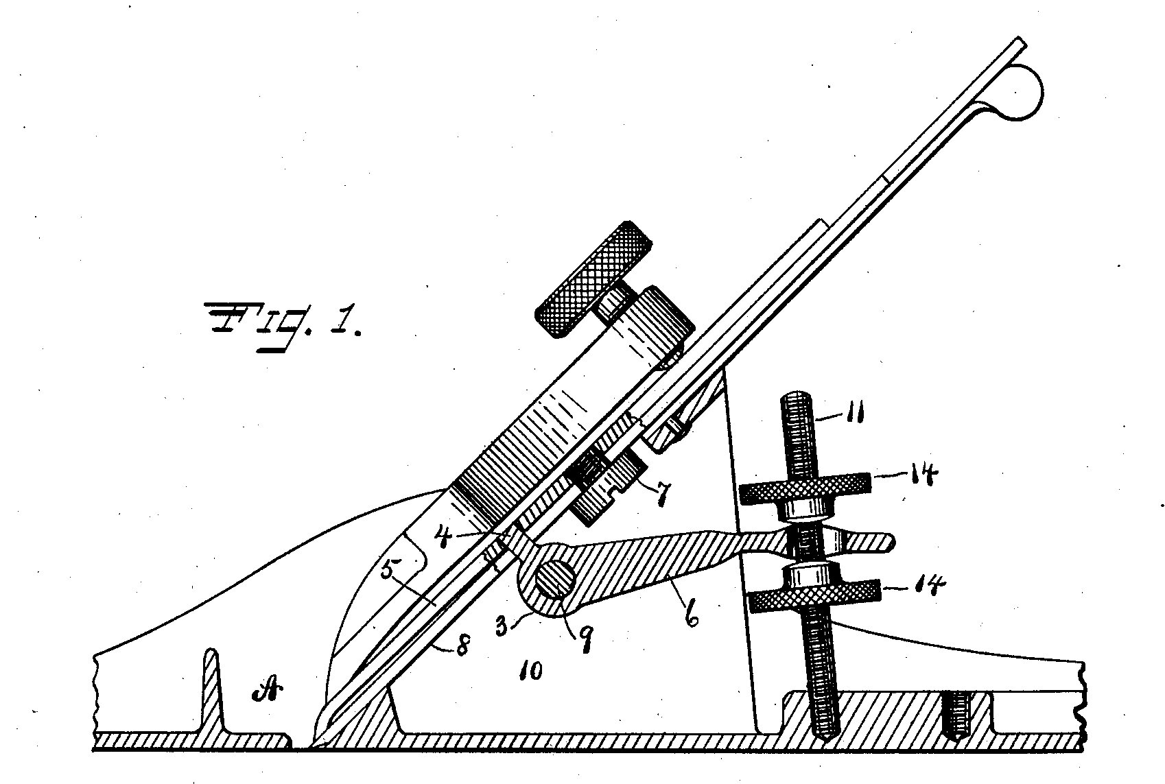
From Patent 763,721


Concept of an open lateral yoke on the post side, never used on an example that has been found. If one is found it should be considered a prototype and you should contact us immediately.
These ILLUSTRATIONS highlight the most important aspects of the X Plane. The components featured in these drawings from the June 28, 1904 patent filing are what set the X Plane well apart from its competition. These features were engineered with one thing in mind, a very vital key to the overall success of a bench plane, Rigidity. Chatter resistance, positive fine depth control with the ability to be locked when the perfect depth has been achieved and common sense lateral adjustment. These things are the basis of this famous feat of engineering.
The chatter resistance of the Union X Planes is unparraleled in that the body acts as a harmonic dampener with two ribs cast into the body itself.(10) These ribs are joined together where the lateral is affixed to a bridge. This bridge serves a few purposes, one being to create a landing for the lateral lever to be attached, the second being a rigid point that keeps the tops of the ribs from moving or swaying under hard use. Not only does the fact the ribs are cast directly into the body help the chatter resistance of the X, they also act somewhat like a tuning fork drawing additional harmonics away from the iron, chipbreaker and lever cap assembly. As most Plane users will tell you a plane that chatters on even the smallest level will suffer from loss of performance.
The way the yoke (6) is attached to the body also has a huge bearing on the strength and rigidity of the plane. A very thick ever so slightly tapered pin (9) is run completely through the cheeks, both ribs and the yoke itself. (X2-X8) This effectively ties the entire middle of the plane together into one unit. Therefore creating a very rigid and harmonic sapping plane!
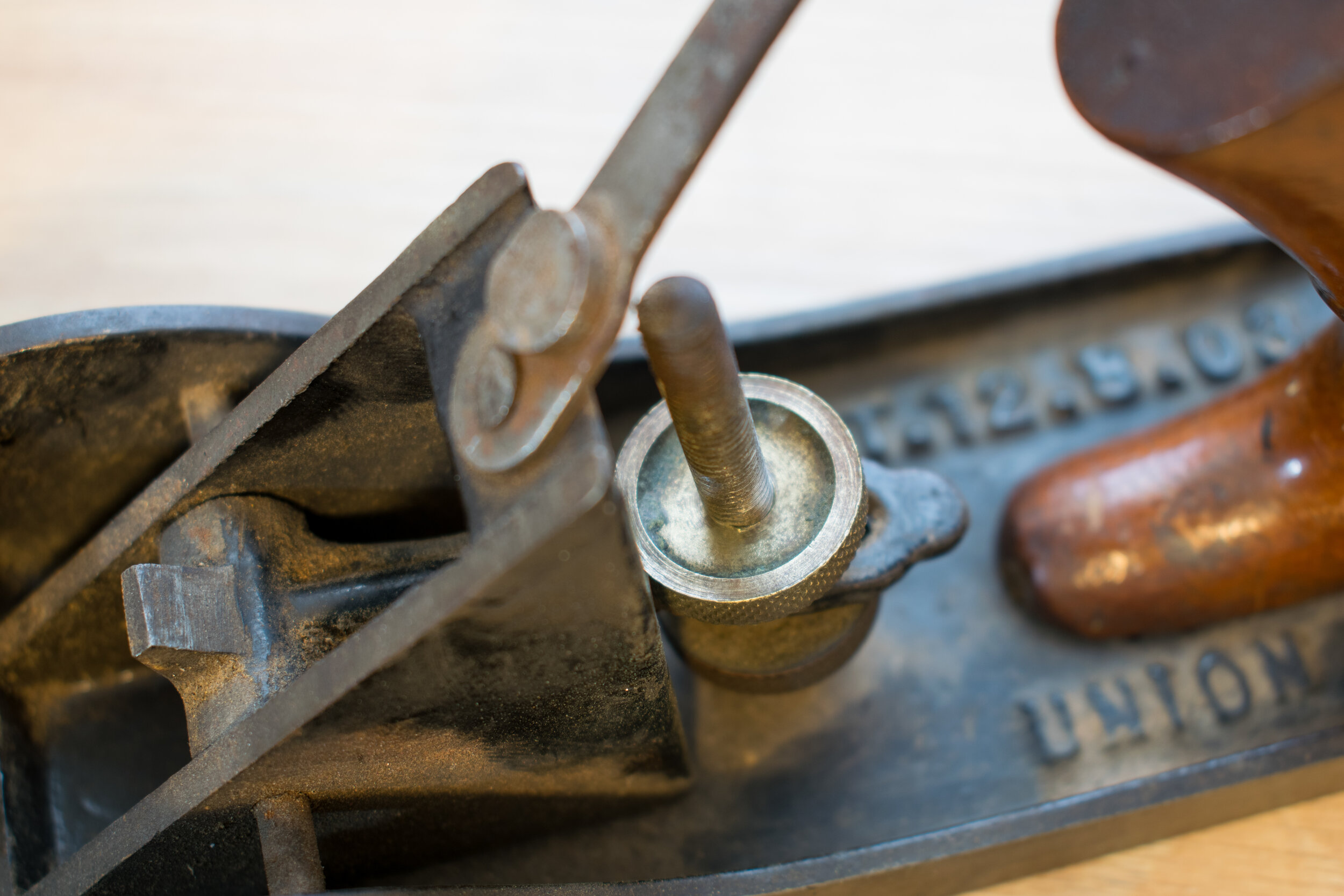
The depth adjustment is precisely controlled via a slightly tipped vertical threaded post, (11) two locking nuts (14) and a yoke lever that is fitted firmly through the entire body. The idea behind these components allows for a completely locked position and no chance for slippage. The yoke engagement between the locking nuts also eliminates the issue with the play found on Bailey pattern planes which uses a single piece depth wheel and most of the time require a multitude of turns before the iron is engaged in either direction. With the X Plane the user slightly loosens one nut and tightens the other to make absolute finite adjustment. Once the required adjustment has been made and the two locking nuts are snug against the yoke there is no chance for movement without loosening one or the other nut.
Before the X Plane users had the wonderful task of turning their plane upside down to adjust the lateral movement of their Bailey pattern planes. While this worked quite well it didn’t make a lot of sense. You push the lateral right and your iron goes right…. Right? No. it goes the opposite way. So Union thought why not make a right push of the lateral make the right side move down and vice versa a left movement goes left? Common sense!
From Patent 746,286


Union Irons are something of a legend among Union Collectors and are highly sought after for their overly robust thickness and outstanding balance of hardness and ductility.
This balance is very important in the function of the X Plane. When a body is this rigid the iron has to accept some of the harmonics to prevent reverberation back into the cutting edge. If the iron is very thick and all hard the harmonics will travel up towards the unsupported edge and cause an even higher reverberation, which would transfer back towards the cutting edge in the form of lower performance and a less than optimal surface finish.
Union has traditionally answered this issue the same as other makers, making the iron hard at the cutting edge back the bottom of the slot and leaving the rest of the iron annealed or “soft”. This is basically a high pitched ring at the cutting edge vs a dull thud at the top where the plane iron is unsupported. For most plane users they will be able relate with the whiiiisp sound made by a well tuned and very sharp plane. This wisp is a harmonic note. In this particular case the higher frequency of a tight grained and hard steel is transferring into the softer looser grained steel which then absorbs some of the harmonic micro-vibration or granular turbulence, that coupled with a rigid cast as one frog and body setup, the harmonics are dampened and completely dissipated as they travel upwards. This gives the plane an advantage over another plane that is dependent solely on a couple of contact points between the frog bottom and frog seat. The lesser plane will have components that separate creating more opportunities for poorly mating surfaces which will enhance harmonics and increase the vibration that causes chatter. While in tuning this can be fixed with good results it does take a bit of skill to tune a two piece plane properly and many are lost each year to poor tuning and “restoration” practices. The simple answer is a one piece construction to start with.
One challenge with such a thick iron is obtaining a positive chipbreaker “grip”. This is where the chipbreaker is being held against the iron face using a chipbreaker screw. It is very important that this is a very secure attachment because the depth of the iron adjustment is dependent on the chipbreaker location. So the Inventors used added a series of “tracks” (13) to the face of the iron where the chipbreaker nut was to come into contact with the bevel side of the iron to prevent slippage and misalignment.
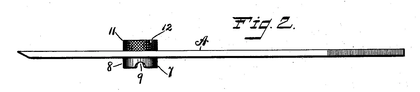
Figures 1, 2, 4, 5, 8 and 9 in the patent drawings show a double nut type configuration. This configuration would allow the iron to be adjusted in the absence of a chipbreaker slot or with a chipbreaker engagement slot. The double nut itself has a slot in which the depth lever can engage and actuate the movement of the iron. No example has ever been found featuring this arrangement and should be considered a prototype if encountered (contact us immediately if an example is located). Original patent paperwork indicates that “no model” was provided for any of the three patents so it COULD be surmised that no prototype was submitted with the patient application. With that being said though, the Stanley Liberty Bell looks eerily similar in design. (See Figure 1 and 2 below)
From Patent 746,285


These drawings also explain a long sought answer to a simple question. “Why do a large number of Union made planes have Patent Applied For on the lateral adjustment lever”. The answer is simple it is featured in the patent application and there were hopes that the lateral would receive patent protection along with the rest of the components. I was not to be though. The lateral lever never received such patent protection.
If you look closely at components 30-32 you will see something very familiar to the above “double-nut” drawing
Figure 1 and 2 feature a plane that was not produced exactly how its drawn and contains a mechanism more similar to a Stanley Liberty Bell bench plane than to a Union Made Plane.
However Figures 5, 6 and 7 are somewhat similar to the 500 series transitional planes produced by Union Mfg Co. The difference being the depth lever does not have a yoke on the end and the mechanism adjusts from the side and not in the middle like the final 500 series planes did. Keep in mind the difference between the 500 Series and full on X Planes was the vertical post and lock nut assembly was on the X Plane and not the 500 series.
The 500 Series came in sizes 502, 515, 537, 539 and 542 The yoke itself is identical to the X yoke.
The X Plane Transitional planes did have the vertical adjuster. The X Plane transitional came is two types, one being a very rare and depicted in the patent drawing (Figure 1 No 5) and the other a more commonly plain X plane adaption from their metallic brothers.
They were offered in sizes (Wood Sole)
X21, X22, X23, X24, X26, X27, X27A, X28, X29, X30, X31, X32, X33, X34, X35, X36 and X37A (Jenny).
Steel Plated Sole (Figure 1 No 5) “S” indicates a Steel Plate on the Sole
(THese Planes are very rare and should be treated as such)
X21S, X22S, X23S, X24S, X26S, X27S, X27AS, X28S, X29S, X30S, X31S, X32S, X33S, X34S, X35S, X36S and X37AS (Jenny).
The lever cap on the X Planes is very thick and robust. The single knurled brass cap screw is very strong and sturdy. The reliefs on the sides of the cap have a positive stop feature to insure the end of the lever cap stops at a predetermined position each and every time which was permanently set at the factory during the manufacturing process. They appear to have been hand fitted at the time with no two falling at exactly the same position from the edge of the chipbreaker and iron cutting edge. The inside of each lever cap will have the planes size compatibility cast in. Its an easy way to determine if a cap from one plane will fit another.
Types and Features
There are 4 Types of X Plane Series.
The Type description highlights changes from the type prior to it.
Type 1
(Union Mfg Co Made)


Large Lever Cap Knurl Nut
The large 1 inch diameter lever cap knurl nuts are only found on the earliest X Planes. This is not unique to Just the Type 1 and can be found on the Type 1A and 1B as well as the Type 2. This nut however tells you the X was made by Union Manufacturing Company and not by Stanley.

Type 1A Patent Applied Stamp
The Type 1A is the earliest of the Type 1’s and can be identified by this feature. The recess has a patent applied for stamp.

Type 1B Patent Date Stamp
The Type 1B will feature a Patent Date stamp in the recesses on the lock nut. This is not unique to the Type 1B by itself and can be found on the Type 2.

Type 1 Patent Date Below Iron Stamp
This stamp is found on both the Type 1A and 1B. This feature is unique to the Type 1’s only.
The Date Stamp is “12-08-03”

Type 1 “Railroad Tracks”
Tracks will be found on the backs of Type 1 Irons as per the patent drawings above. This feature is unique to the Type 1A and Type 1B.
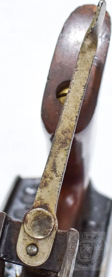
Pat Applied For Lateral Stamp
Type 1’s will have a Patent Applied for Stamp on the lateral adjuster. This feature is not unique to the Type 1 only and can be found on Type 2’s.
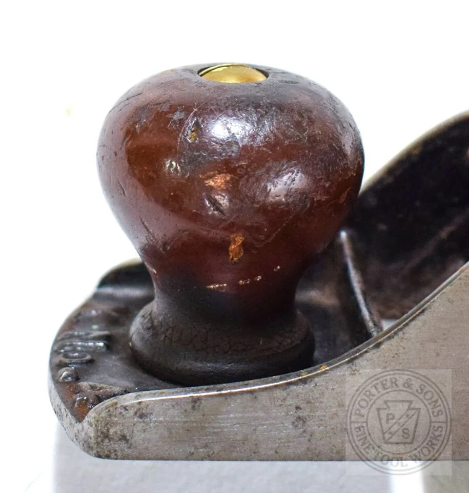
Early Ballon Knobs
The earlier knobs are balloon shaped and are quite large on the larger sizes. They will feature a beaded base detail as well as the Union Style domed barrel nut heads. This feature can be found on both Type 1’s and Type 2’s.

Very Long Slender Horn Totes
Early Unions have what some consider the most beautiful totes because of their slender appearance and very long slim horn. This feature can be found on both Type 1’s and Type 2’s. Type Ones also feature a very small smooth edge teardrop shaped lateral tip. This feature is not Unique to Type 1 and is shared with the type 2.
Types and Features
Type 2
(Union Mfg Co Made)
No patent mark on the Iron

Small smoothed edge teardrop shape similar to the Type 1. Still carries the long skinny horned tote from Type 1.
Types and Features
Type 3
(Stanley Made)

Small diameter cap screw
3/4” Diameter Cap Screw Knurl Nuts.

Unstamped Lock Nuts
No marks should be present in the Locking Nuts by Type 3.
Peened Rivet Lateral Attachment
As with all other Unions prior to Type 3 the Lateral lever is attached via a peened rivet in the bridge. The bridge is a little thicker on the Type 3 as well.

Stanley Shaped Mahogany Tote

Stanley Shaped Mahogany Knob

Stanley Rod Screws

Stanley Rod Screws
Types and Features
Type 4
(Stanley Made)

Lateral Screw
The lateral lever now has a screw fastening it to the bridge instead of utilizing a peened rivet. This was a big improvement over the older X Series planes. The older planes are frequently found with either loose or missing laterals. This feature is unique to the Type 4.

One Piece Tote and Knob Screw
The tote and knob are now held in place with a standard Stanley one piece screw from the era they were made. These planes were likely discontinued after all remaining inventory was exhausted. Likely around 1935.